8 Bit Serial To Parallel Converter Verilog Code

Design of Serial IN - Parallel Out Shift Register using Behavior Modeling Style - Output Waveform: Serial IN - Parallel OUT Shift Register Verilog CODE- //----------------------------------------------------------------------------- // // Title: SIPO // Design: verilog upload 2 // Author: Naresh Singh Dobal // Company: nsdobal@gmail.com // Verilog Programs & Exercise by Naresh Singh Dobal. // //----------------------------------------------------------------------------- // // File: Serial IN Parallel OUT Shift Register using Behavior Modeling Style.v module SIPO ( din,clk,reset,dout ); output [3:0] dout; wire [3:0] dout; input din; wire din; input clk; wire clk; input reset; wire reset; reg [3:0]s; always @ (posedge (clk)) begin if (reset) s.
Hello I am trying to implement a parallel in serial out shift register based on the data sheet for the 74LV165A 8 bit parallel in serial out shift register. The spec sheet may be found at datasheet for 74LV165A. If I make my test bench begin by shifting in serially, then try to latch data on the parallel input the data does not appear. Jan 27, 2013 - Posts about Verilog code for 8bit shift register written by kishorechurchil.
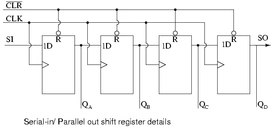
A serial-in, parallel-out shift register is similar to the in that it shifts data into internal storage elements and shifts data out at the serial-out, data-out, pin. It is different in that it makes all the internal stages available as outputs. Therefore, a serial-in, parallel-out shift register converts data from serial format to parallel format. An Example of Using Serial-in, Parallel-out Shift Register If four data bits are shifted in by four clock pulses via a single wire at data-in, below, the data becomes available simultaneously on the four Outputs Q A to Q D after the fourth clock pulse. The practical application of the serial-in, parallel-out shift register is to convert data from serial format on a single wire to parallel format on multiple wires. Let’sl illuminate four LEDs (light emitting diodes) with the four outputs ( Q A Q B Q C Q D). The above details of the serial-in, parallel-out shift register are fairly simple.
Pro-poslovicy has the lowest Google pagerank and bad results in terms of Yandex topical citation index. Over the time it has been ranked as high as 225 599 in the world, while most of its traffic comes from Russian Federation, where it reached as high as 13 347 position. We found that Pro-poslovicy.ru is poorly ‘socialized’ in respect to any social network. Poslovici pro trenie. It was hosted by Beget Ltd.
It looks like a serial-in, serial-out shift register with taps added to each stage output. Serial data shifts in at SI (Serial Input). After a number of clocks equal to the number of stages, the first data bit in appears at SO (Q D) in the above figure. In general, there is no SO pin.
The last stage (Q D above) serves as SO and is cascaded to the next package if it exists. Serial-in, Parallel-out vs. Serial-in, Serial-out Shift Register If a serial-in, parallel-out shift register is so similar to a serial-in, serial-out shift register, why do manufacturers bother to offer both types? Why not just offer the serial-in, parallel-out shift register? The answer is that they actually only offer the serial-in, parallel-out shift register, as long as it has no more than 8-bits.
Note that serial-in, serial-out shift registers come in bigger than 8-bit lengths of 18 to 64-bits. It is not practical to offer a 64-bit serial-in, parallel-out shift register requiring that many output pins. See waveforms below for above shift register. The shift register has been cleared prior to any data by CLR’, an active low signal, which clears all type D Flip-Flops within the shift register. Note the serial data 1011 pattern presented at the SI input. This data is synchronized with the clock CLK.

This would be the case if it is being shifted in from something like another shift register, for example, a parallel-in, serial-out shift register (not shown here). On the first clock at t1, the data 1 at SI is shifted from D to Q of the first shift register stage. After t2 this first data bit is at Q B. After t3 it is at Q C. After t4 it is at Q D. Four clock pulses have shifted the first data bit all the way to the last stage Q D.
The second data bit a 0 is at Q C after the 4th clock. The third data bit a 1 is at Q B. The fourth data bit another 1 is at Q A. Thus, the serial data input pattern 1011 is contained in ( Q D Q C Q B Q A). It is now available on the four outputs. It will available on the four outputs from just after clock t 4 to just before t 5. This parallel data must be used or stored between these two times, or it will be lost due to shifting out the Q D stage on following clocks t 5 to t 8 as shown above.
- вторник 15 января
- 67